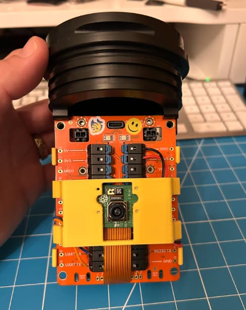
In my previous builds it took me nearly 2 hours to wire up the electronics for RPi + Mote. Most of the time was spent cutting wires, trimming the ends, and solder jumpers between the mote and Pi. Then double checking my work and fixing mistakes. That was a good way to build the first few cameras, but I’d like this to be easier and more reliable so that others could build their own cameras and not have it take so long.
This was the motivation for the “BristlePi”, a PCBA that could sit between the Mote and the RPi and take care of the power and RT/TX wiring for me. I’ve designed a few “expander” boards in the past and used my Othermill to CNC machine copper boards before, but the fine pitch of the mezzanine connector was a challenge so I enlisted the help of a new friend, @TLAW, to help design the board. Tom did all the layout in KiCAD. We reviewed the design files during BristleCon in January before submitting the final files to PCBway in early February.
And five weeks later…the boards have arrived!


For this first rev of the hardware we kept the design simple. It includes:
- 5V regulator to power the Pi
- traces connecting RX/TX lines from the Pi to the Mote
- mounting holes in the corners to secure PCBA to camera shell
- cutout for USB-C cable for debugging
And that’s it.
Assembly, 5 min or less
The Pi gets mounted to the BristlePi with 4x fasteners + spacers then soldered to the 2x20 header. Cheap and easy.

The mote is secured to the “bottom” of the BristlePi with two screws + 5mm tall spacers.


First test
I cloned a copy of the SD card from my blue 3D printed camera using balenaEtcher then inserted the new SD card into the Pi. This way all the code + libraries + hardware configurations get copied over to the new device. The whole process took less than 5 minutes. Much faster than starting with a brand new install of the RPi OS and manually installing all the requirements and repos.
The camera defaults to setting up an Ad-hoc network so users can connect to the Pi directly then SSH in without need for a local wifi network. I wrote a test scrip to verify that the camera was wired up and working correctly. And here is the first test image captured with the BristlePi. It works!

Next Steps
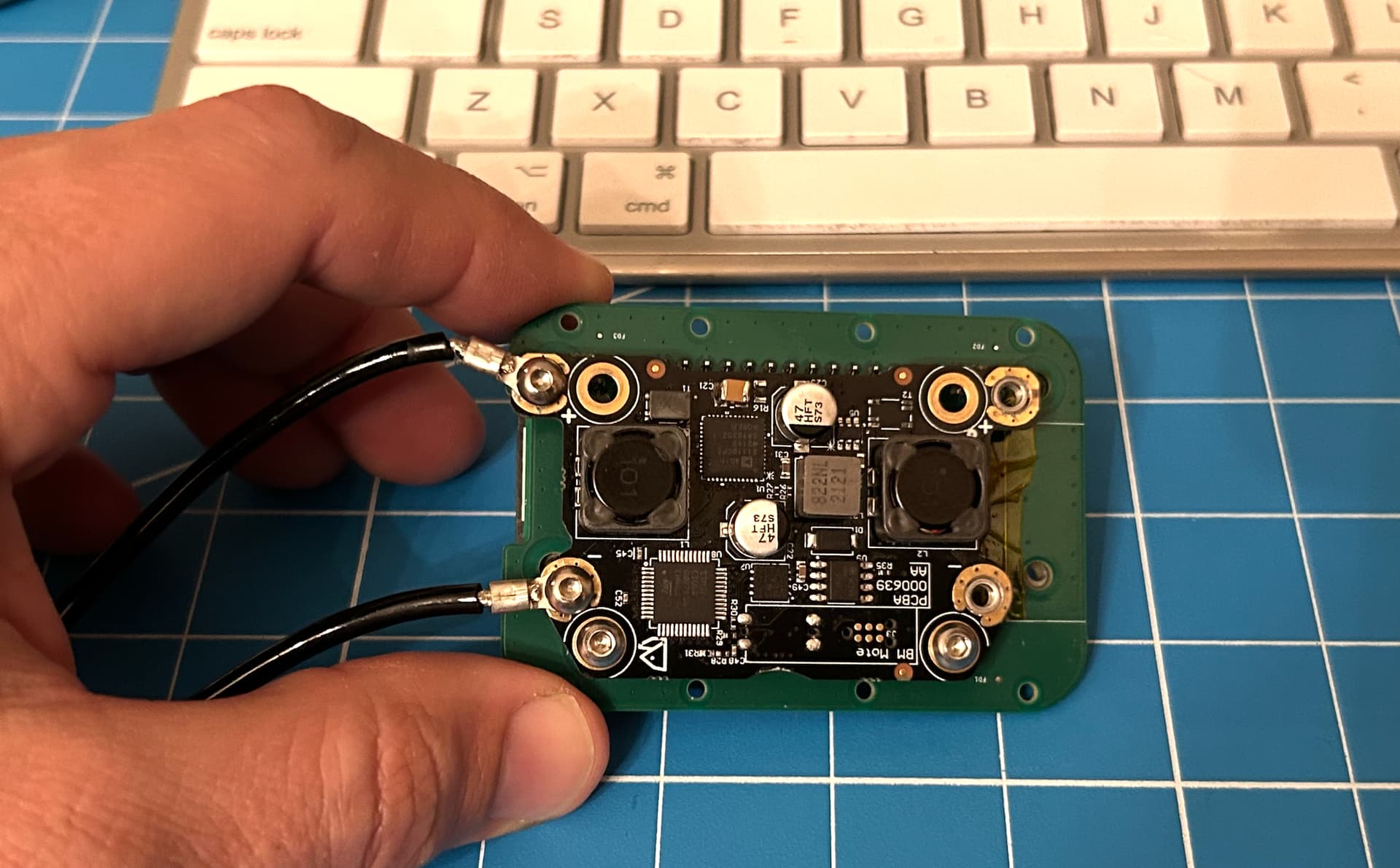
I made a few mistakes with the mechanical layout of the PCBA. I spec’ed the wrong height for the mezzanine connector and now the inductor is coming into contact with one of the threaded standoffs on the mote. I used two pieces of Kapton tape to electrically isolate the inductor for these first five boards - but the next rev will move the inductor out of the way to avoid any electrical issues in the future.

I have some other ideas like adding an RGB LED to help with debugging and perhaps adding a motor driver to power a DC motor for a wiper arm to keep the camera lens clean. @TLAW has plans to add an IMU as well.
Once we work out the bugs and make a few fixes we are planning to make the design files opensource. At that point I think the code for the project will be in a good place to cut a release along with the parsing scripts to decode the messages from the API and stitch the image back together.
Let me know what you think
What features would you want on a BristlePi and how might you use one for your project? Or how might you use an underwater camera?